
Page 1928 - 1.0/2.3 to SHV RF Connector Datasheets
P. 1928
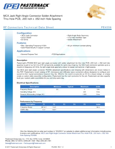
MCX Jack Right Angle Connector Solder Attachment
     Thru Hole PCB, .200 inch x .052 inch Hole Spacing


     RF Connectors Technical Data Sheet                                                                      PE4556


                   Configuration
                       •  MCX Jack Connector                            • Right Angle Body Geometry
                       • CECC 22220                                     • Thru Hole Interface Type
                       • 50 Ohms                                        • Solder Attachment
                   Features
                       • Max. Operating Frequency 6 GHz                 • 30 µin minimum contact plating
                       • Gold Plated Beryllium Copper Contact
                   Applications
                       • General Purpose Test           • PCB Applications
                   .
                   Description
                   Pasternack’s PE4556 MCX jack right angle connector with solder attachment for thru hole PCB (.200 inch x .052 inch hole
                   spacing) is part of our full line of RF components available for same-day shipping. Our MCX jack connector operates up to a
                   maximum frequency of 6 GHz. Its right angle body geometry allows for easier connections in tight spaces.
                   Our  MCX  jack  right  angle  connector  PE4556  datasheet  specifications  and  drawing  with  dimensions  are  shown  below  in
                   this PDF. Pasternack’s broad catalog of RF, microwave and millimeter wave connectors allows designers to configure and
                   customize their signal connections however they like. Whether the need is to provide an I/O for a board design, or simply
                   create a custom cable assembly configuration, Pasternack has the right connector for the job. Pasternack can also expertly
                   build your custom cable assemblies for you and ship same-day.

                   Electrical Specifications

                                 Description              Minimum        Typical       Maximum         Units
                       Frequency Range                       DC                            6             GHz
                       Operating Voltage (AC)                                             335           Vrms
                       Dielectric Withstanding Voltage (AC)                              1,000          Vrms
                       .

                       Performance by Frequency
                            Description        F1         F2        F3         F4         F5           Units
                       Frequency Range       DC to 1     1 to 3                                         GHz
                       VSWR, Max              1.5:1     1.63:1
                       .


                      Click the following link (or enter part number in “SEARCH” on website) to obtain additional part information including price,
                      inventory and certifications: MCX Jack Right Angle Connector Solder Attachment Thru Hole PCB, .200 inch x .052 inch
                      Hole Spacing PE4556


                                                        PE4556  REV 1.3                                                1