
Page 2952 - RF Attenuator Datasheets
P. 2952
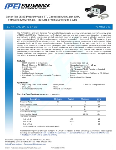
Bench-Top 95 dB Programmable TTL Controlled Attenuator, SMA
          Female to SMA Female, 1 dB Steps From 200 MHz to 6 GHz


      TECHNICAL DATA SHEET                                                                           PE70A5013


                   The PE70A5013 is a 50 ohm Benchtop Programmable Step Attenuator assembly which operates over the frequency range
                   of 200 MHz to 6000 MHz.  This instrument has 2 indivitually controlled solid state programmable attenuators that each have
                   a range from 0 to 95 dB.  Insertion loss is 8.0 dB typical with maximum average input power of +20 dBm.  Additonal typical
                   performance includes +/- 1.0 dB attenuation accuracy and switching speed of 1 microsecond.  The DC supply is +12 Vdc
                   with a 100-240 VAC AC/DC transformer included.  Note that both attenuators can be connected in series to attain higher
                   attenuation levels, but this perofrmacne is not guaranteed.  The design features 2 lever swtiches on the front panel that
                   includes digital readouts and SMA female RF input/output ports.  Both switches are manually adjustable in 1 dB step sizes
                   with either tap to step or hold to jog functions.  These 2 swtiches can work simultaineously to perform manual handover tests.
                   The design can also be command controlled remotely by exicutable test scripts using Ethernet (RJ45 Female) or RS-232
                   (serial contorl) connector interfaces.  The Ethernet, RS-232, and manual interfaces can all be utilzed simultaneously without
                   blocking other users from using the test system.  The firmware can handle up to 12 network connections.  A comprehensive
                   user manual is available to download.

                   Features
                       •  200 MHz to 6000 MHz Bandwidth                  •  Insertion Loss: 8 dB typ
                       •  Manual, Ethernet, or RS-232 Controlled         •  Attenuation Accuracy: +/- 1 dB typ
                       •  0-95 dB attenuation                            •  Max Average Pin: 20 dBm
                       •  1 dB Step Size                                 •  +12 Vdc supply (AC/DC Transformer Included)
                       •  50 Ohms                                        •  SMA female connectors
                       •  Swithing Speed: 1 microsec                     •  Remote Control: Ethernet RJ45 port or RS-232 port
                       •  2 Indivitually Controlled Programmable Step Attenu-  in rear
                        ators                                            •  Downloadable User Manual


                   Applications
                       •  Engineering Test & Measurement   •  Military Radio             •  Wireless Fading Simulation
                        (ATE) Labs                      •  Radar
                       •  Communications Systems        •  Wimax & 3G Simulators


                   Electrical Specifications (Values at 25°C, sea level)

                                 Description              Minimum        Typical       Maximum         Units
                       Frequency Range                       0.2                           6            GHz
                       Mean Attenuation Range                 0                           95            dB
                       Insertion Loss                                       8             8.5           dB
                       Input VSWR                                                         2:1
                       Survival Power Average                                             +25           dBm
                       Power Handling Capacity                                          +20 CW          dBm
                       Accuracy of Attenuation
                                 1 dB to 3 dB                              ±0.5                         dB
                                 4 dB to 7 dB                              ±0.75                        dB
                                 8 dB to 11 dB                              ±1                          dB
                                 12 dB to 95 dB is ±1.25 dB or 4% whichever is greater

                      Click the following link (or enter part number in “SEARCH” on website) to obtain additional part information including price,
                      inventory and certifications: Bench-Top 95 dB Programmable TTL Controlled Attenuator, SMA Female to SMA Female,
                      1 dB Steps From 200 MHz to 6 GHz PE70A5013


                                                       PE70A5013  REV 1.0                                              1