
Page 2271 - 1.0/2.3 to SHV RF Connector Datasheets
P. 2271
MMBX Jack Snap-On Connector Solder Attachment
Surface Mount PCB, With Female Center Contact
RF Connectors Technical Data Sheet PE45262TR1
Typical Performance Data
SOLDER PROCEDURE FOR MMBX RECEPTACLE
1) Deposit solder paste ‘SnAg4Cu0.5’ on mounting zone by screen printing application.
We recommend a low residue flux.
We advise a thickness of 150µm.
2) Placement of the receptacle on the mounting zone with an automatic machine of ‘pick and
place’ type.
A video camera is recommended for positioning of the component.
Adhesive agents must not be used on the receptacle.
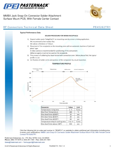
3) This process of soldering has been tested with convection oven. Below please find, the typical
profile to use.
4) Verification of solder joints and position of the component by visual inspection.
TEMPERATURE PROFILE
Parameter Value Unit
Temperature rising area 1 - 4 °C/sec
Max Peak Temperature 260 °C
Max dwell time @260°C 10 sec
Min dwell time @235°C 20 sec
Max dwell time @235°C 60 sec
Temperature drop in cooling area -1 to -4 °C/sec
Max dwell time above 100°C 420 sec
Click the following link (or enter part number in “SEARCH” on website) to obtain additional part information including price,
inventory and certifications: MMBX Jack Snap-On Connector Solder Attachment Surface Mount PCB, With Female Center
Contact PE45262TR1
PE45262TR1 REV 1.0 3